
位姿包括平移和旋转,相比平移,旋转要复杂很多。理解了如何计算旋转,平移也就差不多得到结果了。看这篇文章时,请同时打开“LocalTrajectoryBuilder2D::AddRangeData”,函数AddRangeData可说执行了cartographer计算local_pose的整个过程。
公式Pose-1(计算new时刻旋转值):
公式Pose-2(old到new之间旋转变换量):
:new时刻旋转值。
:old到new之间旋转变换量。
:old时刻旋转值
- 零时刻。收到一次点云数据、最后一个点的采集时刻。因为在表示该点的point_time.time时,值总是0,所以称为零时刻。在LocalTrajectoryBuilder2D执行AddPose时,加的是这个时刻的机器人位姿。
- timed_pose_queue_至少得存在两个pose,因为要由首、尾两个pose算出瞬时角/线速度。只有一个的话,做为除数的时间间隔是0,就没意义了。
- 总会通过timed_pose_queue_中的首、尾两个pose的变化量除以时间间隔算出瞬时角速度,放在angular_velocity_from_poses_。当use_imu_data=false时,它直接赋值给imu_tacker_的imu_angular_velocity_。
- 存储瞬时角度速用的是旋转向量,既然是由“四元数/queue_delta”生成,使用时又要先转成四元数,中间为什么要用旋转向量?——可能是瞬时角度速同时要用于表示从硬件imu读出的角速度,那里的值是用旋转向量格式。对如何表示旋转向量,Eigen往往用Eigen::AngleAxisd,cartogrphaer没用它,而是Eigen::Vector3d,它的[0]、[1]、[2]分别对应旋转向量的roll、pitch、yaw。carotographer自实现的RotationQuaternionToAngleAxisVector用于把四元数转成旋转向量,AngleAxisVectorToRotationQuaternion则把旋转向量转成四元数。
- 处理一次点云后,会生成两个pose:存储在timed_pose_queue_的local_pose和存储在imu_tracker_的imu-pose。
- gravity_alignment类型transform::Rigid3d,这个是包括平移和旋转的3维刚体变化,但平移部分总是(0, 0, 0)。
- use_imu_data=false时,假设不执行ScanMatch,即把pose_prediction直接赋值给pose_estimate_2d,任何变量中的平移向量都会是0。
一、如何计算旋转
只看代码会很抽像,尤其是涉及到算法部分。这里给出运行过程中收到两次点云时,计算旋转涉及到的变量值。示例场景是2D、use_imu_data=false。SLAM传感器是思岚RPLIDAR A1M8,每次点云采集时有720个点。处理第k次点云后,机器人位姿yaw=47.56414度,处理第k+1次后,机器人位姿yaw=53.10242度。以下解释代码时,会结合收到第k+1次点云时数值。
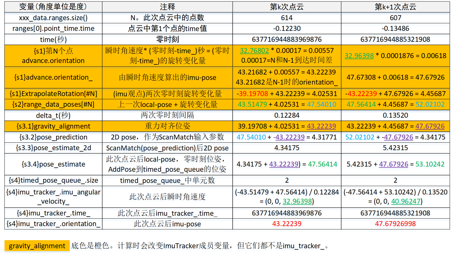
步骤1、计算两次零时刻之间旋转变化量,数值等于ExtrapolateRotation[#N]
变化量=瞬时角速度 * abs(ranges[0].point_time.time)。但没按这个公式一次性计算,而是进行了N-1次。这么做的原因是顺便算出点云中N个点的旋转值。在cartographer认为,“应该”由硬件imu数值算出这个变化量。“应该”加引号是会存在use_imu_data=false,那时硬件imu数值其实纯粹由软件pose计算。
步骤2、得到第k次点云零时刻的未优化local_pose,放在non_gravity_aligned_pose_prediction
值等于点云中第N个点的range_data_poses[#N],计算方法local_pose[#k-1] + ExtrapolateRotation[#N]。
步骤3、将non_gravity_aligned_pose_prediction进行优化,得到local_pose
- 计算gravity_alignment。gravity_alignment = imu-pose[#k-1] + 瞬时角速度 * (time[#k] - time[#k-1])。若(time[#k] - time[#k-1])和接近abs(ranges[0].point_time.time),那gravity_alignment值基本等于之前计算range_data_poses[#N]过程中“由瞬时角速度算出的imu-pose”。在cartographer认为,“应该”由硬件imu数值算出这个变化量。
- 得到gravity_alignment后的2d旋转。pose_prediction = Project2D(non_gravity_aligned_pose_prediction - gravity_alignment)。gravity_alignment变化,直观可认为是原pose减去一个imu数值算出的pose,逆gravity_alignment则是加回这个pose。
- 执行非线性优化ScanMatch。pose_prediction由得到pose_estimate_2d,后者也是个2D旋转。
- pose_estimate_2d增加到3d,逆gravity_alignment,得到local_pose。local_pose = Embed3D(pose_estimate_2d) + gravity_alignment。
步骤4、已算出local_pose,更新相关变量,以用于后面的k+1次点云
- timed_pose_queue_。timed_pose_queue_至少得存在两个pose,因为要由首、尾两个pose算出瞬时角/线速度。只有一个的话,做为除数的时间间隔是0,就没意义了。
- 以软件纯pose算出的瞬时角速度angular_velocity_from_poses_。从首、尾两个pose的变化量除以时间间隔算出瞬时角速度。当use_imu_data=false时,它直接赋值给imu_tacker_的imu_angular_velocity_。
- imu_tracker_中的time_和orientation_,后者就是imu-local。
要理解如何计算旋转不是件容易的事,以上只是说了大概,详细的就需要深入“LocalTrajectoryBuilder2D::AddRangeData”。
二、gravity_alignment
gravity_alignment(重力因子)是代码中一个变量,但也认为是称为重力校正的操作。gravity_alignment类型transform::Rigid3d,这是个包括平移和旋转的3维刚体变化,但平移部分总是(0, 0, 0)。
要执行重力校正原因是接下要调用ScanMatch。对ScanMatch,参数pose_prediction是位姿误差,直观上理解,重力校正可让输入位姿中的旋转变成个较小值,这个较小值称为位姿误差。参数filtered_gravity_aligned_point_cloud是odom坐标系下的点云,注意,不是base_footprint。可以设想种极端极况,当位姿误差pose_prediction是0时。ScanMatch中不论实时相关性扫描优化,还是Ceres优化,都是通过以下公式计算点云在odom坐标系下新坐标。
transform是参数pose_prediction,它不涉及base_footprint和odom坐标系之间的变换,只是odom坐标系中的点乘上位姿误差而已。
为什么要重力校正,这有篇文章:cartographer点云匹配时为什么要重力对齐?
注意:位姿相乘时要严格区分左乘、右乘,相乘次序决定了变换次序。
2.1 重力校正。
重力校正后,点云坐标依旧是三维。
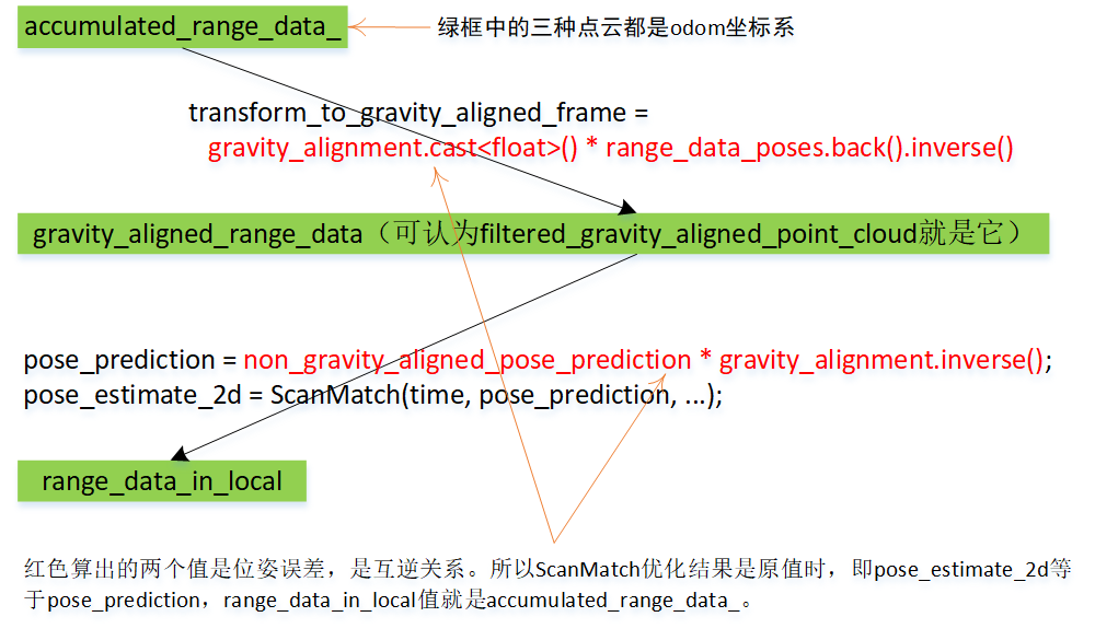
transform::Rigid3f transform_to_gravity_aligned_frame =
      gravity_alignment.cast<float>() * range_data_poses.back().inverse();

sensor::RangeData gravity_aligned_range_data =
      transform_to_gravity_aligned_frame * accumulated_range_data_;
transform_to_gravity_aligned_frame是修正因子,左乘上它,这是把odom坐标系下的点云(accumulated_range_data_)依次做两次坐标变换,第一次变换是range_data_poses.back().inverse(),第二次变换是gravity_alignment。经过第一次变化后,点云会“恢复”到base_footprint坐标系下的坐标。恢复加引号,是因为只最后一个点完全一样,其它点的值有微小偏差。gravity_alignment中平移总是0、只有旋转,可直观想象为是在第一次变化后的基础上逆时针旋转gravity_alignment.rotation度。经过这两次变化后的点云(gravity_aligned_range_data)将送入优化器。
2.2 重力恢复
const transform::Rigid2d pose_prediction = transform::Project2D(
      non_gravity_aligned_pose_prediction * gravity_alignment.inverse())
pose_prediction包含两次坐标变换。对第一次变换non_gravity_aligned_pose_prediction,它来自参数time是零时刻的extrapolator_->ExtrapolatePose(time),就是range_data_poses.back()。所以它就是transform_to_gravity_aligned_frame的逆运算。点云gravity_aligned_range_data左乘上它后,就是accumulated_range_data_。
当然,实际逻辑是位姿误差pose_prediction要送入ScanMatch,得到一个优化后的误差pose_estimate_2d。
sensor::RangeData range_data_in_local =
      TransformRangeData(gravity_aligned_range_data,
                         transform::Embed3D(pose_estimate_2d->cast<float>()));
有了上面结论:pose_prediction就是transform_to_gravity_aligned_frame的逆运算。下面这语句就容易理解了,range_data_in_local是经过ScanMatch优化后的accumulated_range_data_,也是一个基于odom坐标系的点云。作为特例,当ScanMatch优化结果是原值时,即pose_estimate_2d等于pose_prediction,range_data_in_local值就是accumulated_range_data_。
2.3 pose_estimate
pose_estimate是base_footprint到odom的tf,也是作为cartographer规划出的local pose。
  const transform::Rigid3d pose_estimate =
      transform::Embed3D(*pose_estimate_2d) * gravity_alignment;
对特殊情况,当ScanMatch优化结果是原值时,即pose_estimate_2d等于pose_prediction,让代入以上语句。
pose_estimate = non_gravity_aligned_pose_prediction * gravity_alignment.inverse() * gravity_alignment;
结果是pose_estimate“等于”non_gravity_aligned_pose_prediction,即extrapolator_->ExtrapolatePose(time)。
2.4 ScanMatch优化的是位姿误差(imu_pose - local_pose1),而不是位姿
一方面,由里程计设备可得到time时刻平移,由IMU设备可得到time时刻旋转,它们可组成硬件在time时刻的位姿(gravity_alignment),记为imu_pose。另一方面,cartographer分析一次次点云数据,从看到的障碍物情况又算出一个位姿(non_gravity_aligned_pose_prediction),记为local_pose1。这两个位姿就存在一个误差pose_prediction。ScanMatch优化的是pose_prediction这个位姿误差,而不是位姿。
对既没有里程计设备,也没有IMU设备使用场景,像rose_ros,那它计算gravity_alignment纯粹靠的就是通过timed_pose_queue_算出的瞬时角度速、瞬时线速度。这时每收到一帧点云时,non_gravity_aligned_pose_prediction和gravity_alignment变化量是一样的,但由于基数不一样,导致加出来的结果不一样。而且,经过ScanMatch后,位姿误差不会再是pose_prediction,这个优化后误差加上gravity_alignment就是local_pose。
重力修正因子数值的物理意义是由硬件里程计+IMU设备得到的机器人位姿。相应地,gravity_aligned_range_data就是乘上位姿误差后的点云。由于硬件位姿和local_pose接近,该点云看去就是odom坐标系下的点云。
range_data_poses.back()和non_gravity_aligned_pose_prediction用的都是extrapolator_->ExtrapolatePose(time),参数time指零时刻,它们值一样。
三、更新旋转值
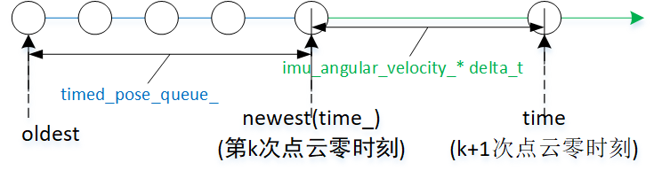
AddRangeData会经常执行一个操作:更新旋转。让以图3为例,已知time_时的旋转old-pose,如何求time时的旋转new-pose?根据“公式Pose-1”,要算出new-pose,就是old-pose乘以time_到time这段时间的旋转变化量。为直观,让以ImuTracker::Advance为例,看cartographer是如何更新旋转。Advance计算旋转变化量的方法是瞬时角速度乘以时间间隔。
Advance功能是把ImuTracker状态更新到指定时刻time,状态包括指示旋转值的orientation_,以及time_、gravity_vector_。
void ImuTracker::Advance(const common::Time time) {
  // Advance只会时间前向更新
  CHECK_LE(time_, time);
  // 求出此次更新要加上的时间间隔delta_t。
  const double delta_t = common::ToSeconds(time - time_);
  // 角速度(imu_angular_velocity_)乘以时间(delta_t),结果是这段时间的角度变化量。
  // imu_angular_velocity_类型是Eigen::Vector3d,但是个旋转向量,乘上标量后仍是旋转向量。
  // AngleAxisVectorToRotationQuaternion把旋转向量转成四元数。
  // 结合图1,此个乘积对应{s1}advance.orientation:32.96398 * 0.0001876 = 0.00618。
  const Eigen::Quaterniond rotation =
      transform::AngleAxisVectorToRotationQuaternion(
          Eigen::Vector3d(imu_angular_velocity_ * delta_t));
  // 以old-pose(orientation_)乘上旋转变化量,得到new-pose。物理意义上,两四元素相乘等价角度相加。
  // 结合图1,此个乘积对应{s1}advance.orientation_:47.67308 + 0.00618 = 47.67926。
  orientation_ = (orientation_ * rotation).normalized();
  // 更新重力方向。对2D来说,不会改变gravity_vector_,仍是初始值(0, 0, 1)。
  gravity_vector_ = rotation.conjugate() * gravity_vector_;
  // 更新时间
  time_ = time;
}
imu_angular_velocity_类型是Eigen::Vector3d,但它其实是个旋转向量。对如何表示旋转向量,Eigen往往用Eigen::AngleAxisd,cartogrphaer没用它,而是Eigen::Vector3d,它的[0]、[1]、[2]分别对应旋转向量的roll、pitch、yaw。carotographer自实现的RotationQuaternionToAngleAxisVector用于把四元数转成旋转向量,AngleAxisVectorToRotationQuaternion则把旋转向量转成四元数。
在图3,标识oldest、newest是想表述这是个timed_pose_queue_,队列中已有4个pose。这时新来第k+1次点云,该如何计算第k+1次点云pose。